In this post and video we will find out how engine sensors work. Magnetic inductive sensors are very common and are used as crankshaft sensors, camshaft sensors, vehicle speed sensors etc. Let’s look at exactly how they are made and how they work.
The video consists of the following:
- Why it’s important to understand how magnetic inductive sensors work
- Common uses for magnetic inductive sensors
- How magnetic inductive sensors are constructed and how they work
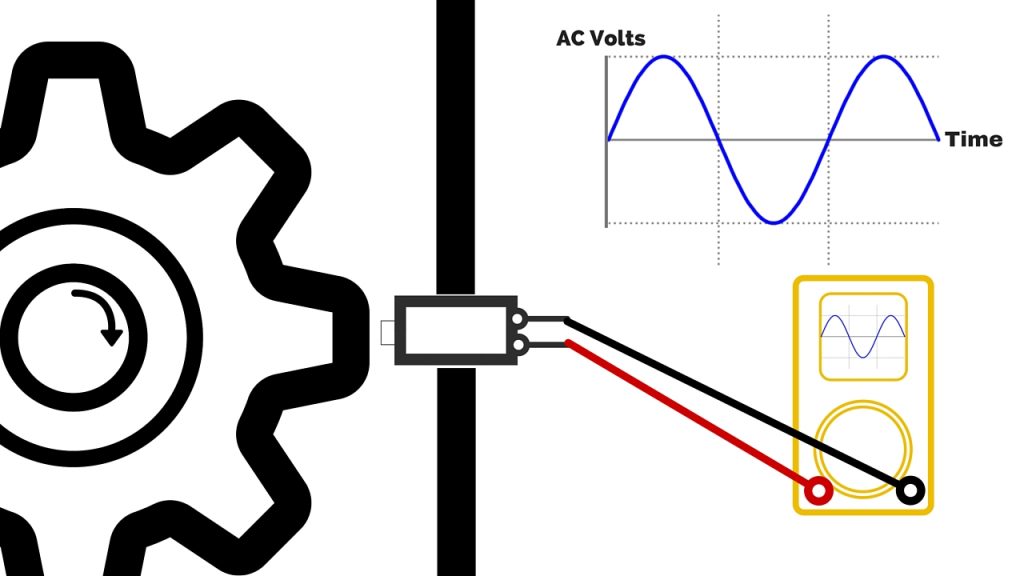
- A practical experiment showing an AC voltage being produced
- A real world example of how an engine sensor is fitted to and works in a modern engine
- Another practical experiment using household objects showing how a crankshaft sensor works
- Some simple fault-finding tests you can use to test an engine sensor
Watch my video ‘How engine sensors work. Crankshaft, camshaft, ABS. Magnetic inductive sensors.’
Magnetic inductive sensors are very commonly used on modern vehicles and their failure can cause all kinds of problems: Difficulty starting, acceleration problems, engine speed ‘hunting’, increased fuel consumption and even the engine cutting out while driving.
Knowing how these sensors work can help you to fix the problems above.
Typical fault codes (a.k.a. trouble codes / error codes) caused by this kind of sensor:
- P0335 Crankshaft sensor CKP (P0336, P0337, P0338, P0339, P0340, P0341, P0342, P0343, P0344, P0345, P0346, P0347, P0348, P0349. If the engine does not run, additional codes may be stored: P0300 Misfire detected)
- P0340 Camshaft sensor CMP (P0345. Related codes: P0300 Misfire, P0725 Engine speed sensor)
- P0500 Vehicle speed sensor (P0501, P0502, P0503)
If you want to buy an OBD II code reader, so that you can read AND clear codes on your car, you can buy a fantastic model at a great price here: https://amzn.to/2weAD3w
Things to check if you suspect a bad sensor:
- Visual inspection of associated wiring.
- Resistance check of the sensor as shown in the video. The exact specified resistance for your sensor will vary depending on the sensor (you may be able to find this online) but if you see an open circuit or short circuit on the copper winding, the sensor is unserviceable and will need to be replaced.
- Signal check. An oscilloscope will show the full picture of what signals are being outputted whilst the engine is turning over but a multi-meter can be used and will show a small AC voltage when the sensor is detecting reluctor movement, as shown in the video.
If you find an open circuit or dead short on the copper winding then the sensor is definitely unserviceable and needs to be replaced. However, please bear in mind that there are many factors at work so you may not always see a fault when testing one of these sensors. The distance between the sensor and reluctor is very small and this air gap is critical to the correct operation of the sensor. Differential thermal expansion can occur when the engine is hot, altering the air gap and even affecting sub-components within the sensor, such as the copper winding. Permanent magnets are also affected by heat and become ‘less magnetic’ at higher temperatures. Problems can also occur if metallic debris collects on the end of the pole pin, altering the voltage produced by the sensor.
What the ECM sees as a ‘normal’ or ‘abnormal’ reading from a sensor may be exactly on the threshold of what your sensor is outputting in real-world conditions. This can cause intermittent problems and can also make fault-finding much more difficult.
Bearing all of the above points in mind it is a wise investment to buy a new sensor that is of the same specification as that originally fitted. Poor quality aftermarket parts may fail after a short time, due to the fine tolerances involved. You don’t have to buy the sensor directly from your car manufacturer, but if your vehicle manufacturer uses a certain type of Bosch sensor, for example, you would be wise to use a replacement Bosch sensor, regardless of where you get it from. In this way you can be confident that the part you are fitting has been manufactured to the exact specifications and tolerances required.
Often if you replace a sensor yourself you will spend less for the entire job than you would for a garage just to identify the fault for you. Check out my other post and video showing how to replace an engine sensor yourself and save some money!
Do you have any comments, suggestions or feedback? If so, please comment below.
I hope you found this post useful. If so, please share it on social media to help me put food on our dinner table.
Cheers!
Chris 👍
![]()


Leave a Reply